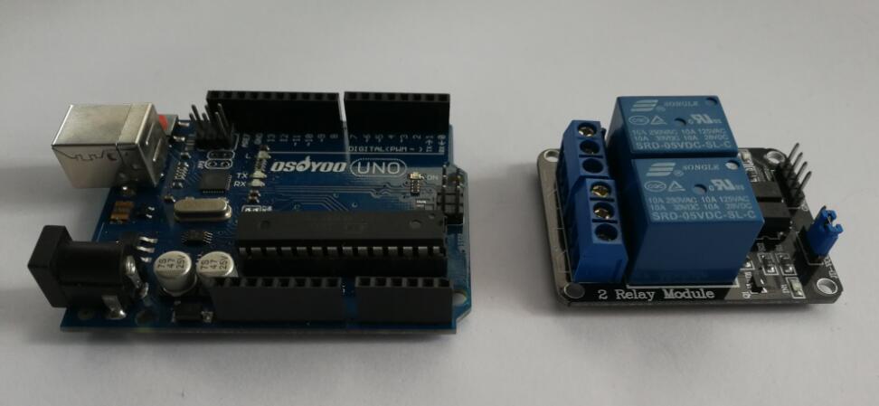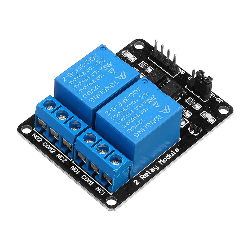

Attach Arduino GPIO pins to each "CHx" pin. On header-2, attach a seperate 5V supply with 5V to "DC+", and ground to "DC-". Wawa July 22, 2019, 5:16am 7 Thats a proper relay module, with everything on it. 2) When a relay switches, high voltage spikes occur on the relay coil. So you need a transistor/fet/optocoupler to amplify the signal. On header-1, attach 'Arduino 5V' to the center, unlabeled pin. 1) Relays draw more power than an arduino pin can deliver. What Are the Types of Relays There are many different types of relays used in electrical systems which are differentiated based either on their poles and throws or their working principle. An additional "CHx" pin is provided for each relay on the module. The special feature of a relay module is that it is compatible with Arduino because it operates on 5 Volts that an Arduino board can support. A second header, header-2 has pins labeled "DC+", "DC-", and "CH1". Attach the cathode to the 12V input and the anode to the ground of the load device.ĭesign 2 is distinguished by a jumper used on header-1 with one pin labeled "H", the middle pin is unlabeled, while the third pin is labeled "L". WARNING: Be sure to use a flyback diode across any loads with a coil, such as a water valve.

The ground of the load is attached to the ground of the 12V supply.) (For example, for a 12V Water Valve, use a 12V Supply with 12V power to "COM". The 16-channel relay module is equipped with transistors, diodes and optocouplers to switch higher loads safely, reliably and with low current. The relays will be activated by a "LOW" signal.Įach relay has outputs labeled "NO", "COM", and "NC".

Attach each GPIO pin from Arduino to each "INx" pin on the Relay Module. On header-2, attach 'Arduino 5V' to "Vcc". For example, if using a 5V relay module, connect 5V to "JD-Vcc", and ground to "GND". On header-1, attach a seperate voltage supply to "JD-Vcc" and "GND". An additional "INx" pin is provided for each relay on the module. A second header, header-2 has pins labeled "GND", "IN1", and "Vcc". For example, if it is to supply a heating resistor, it is better to have the circuit open if the relay does not work correctly anymore.Here are the notes I've made for future reference:ĭesign 1 is distinguished by a jumper used on header-1 with three pins labeled "JD-Vcc", "Vcc", and "GND". When the relay is activated, the circuit will open, and the connected device will no longer be powered.Ĭhoosing the least dangerous mode is safer in case of a control failure (or if the relay is out of service). On the other hand, by choosing the terminals COM and NC, the circuit will be closed by default (when the relay is not activated): the device is switched on. The circuit will be closed only when a signal is sent to the relay. By choosing NO, the relay will be open by default (the electrical circuit will not be closed). The device in the circuit will be connected to the terminal COM and NO or NC depending on your application. NO → Normally Open: Normally Open contact. Relay module for Arduino is one of the most powerful application for Arduino as it can be used to control both A.C and D.C devices by simply controlling the. The relay has a 3-pin terminal block on the power side:ĬOM → the middle pin is called common (COM). The last pin, represented by -, is the ground connected to a pin GND. The middle pin is the power supply connected to the 5V of the ESP32 (3V3 if it is the SRD- module 03VDC -SL-C). It allows sending a signal to drive the relay. The pin S, on the left, is connected to a pin of the ESP32 (here GPIO32 ). On the model SRD-05VDC-SL-C, there are three pins to drive the relay: So if you plan to drive several power circuits separately in one project, it is more interesting to take a multi-relay module. Generally, they come in 2 categories: a module with a single relay and another with several relays simultaneously. In most Arduino kits, the modules use the SRD-05VDC-SL-C from the manufacturer Songle. It is used to programmatically control on/off the. They are typically used in industrial applications to control high power circuits, but it is also used in cars, homes and other electric applications. Very briefly, it’s a mechanical switch that you control via the ESP32 to turn on/off a strong DC electrical circuit (RGB led strips, pumps) or a device connected to the 220V mains (fans, lights, heater, motor…). A relay is a programmable electrical switch, which can be controlled by Arduino or any micro-controller. Relays Relays allow low-power microcontrollers to handle circuits that uses much higher power than what the board can handle directly. In that case, you should consult a:ref:` more theoretical article on how a relay works `. Suppose you have never used a relay before or are curious to understand how it works, its use cases and its limitations. I strongly encourage you to take a ready-made module that integrates the relay with its minimal circuit rather than using the relay alone and making the circuit for the logic part yourself (the relay itself does not fit on a breadboard and should not be put on it anyway).


 0 kommentar(er)
